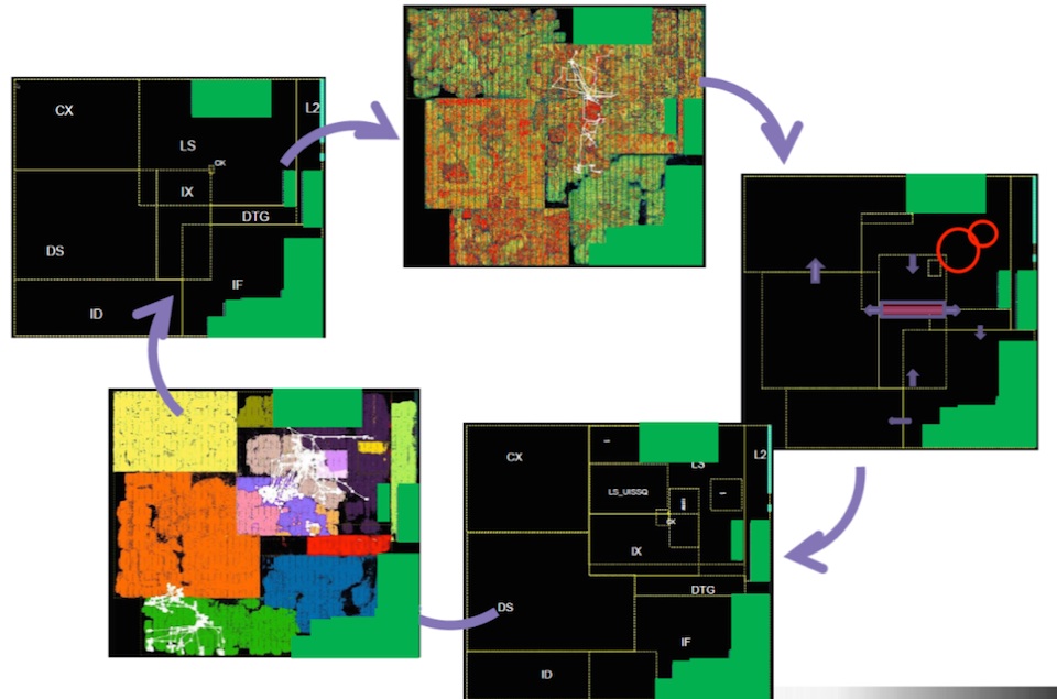
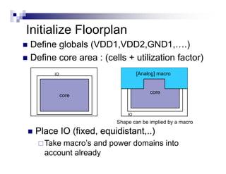
Can macro be placed between core and die boundary or in IO pad. Creating and developing a physical model of the design in the form of an initial optimized layout Because floorplanning significantly affects circuit timing and performance especially for complex hierarchical designs the quality of your floorplan directly affects the quality of your final design Calculation of Core Die size and Aspect Ratio.
Using Optimized Design Flows To Meet Ppa Goals For Soc Cores
To see the core utilization click button in the toolbar and drag and make a rectangle containing the core region.

. You can specify a. Floorplanning Die Size Size Utilization Metal Stack-up Choosing the die size initial standard cell utilization and metallization scheme involves several design tradeoffs Schedule Cost Performance Larger die Easier to route less congestion lower cap decrease signalpower integrity related problems faster design problems cycle Higher cost higher. What is core limited and pad limited design.
What are the guidelines for macro placement. What is placement. The smaller the number the more space is left for routing.
A core utilization of 08 means that 80 of the area is available for placement of cells whereas 20 is left free for routing. If the name of a cell is not present in the current design it will consider as physical only cells. The tool determines the location of each of the components in digital design standard cell instantiations on the.
The number is calculated as a ratio of the total cell area for hard macros and standard cells or soft macro cells to the core area. Core utilization Core utilization standard cell area macro cells area total core area A core utilization of 08 means that 80 of the area is available for placement of cells whereas 20 is left free for routing. Cadence Internal Use Only Quiz.
Sánchez Portland State University esanchezpdxedu Joe Kowalski Portland State University Let us know how access to this document benefits you. Leaves space for. Physical Design Flow IIPlacement.
We define Core Size By or Die Size By where core size by is defined by aspect ratio HeightWidth and core utilization or dimension where we define height and width of core. These cells are not present in the design netlist. If core utilization of 08 means that 80 of the area is available for placement of cells whereas 20 is left for routing.
A core utilization of 08 for example means that 80 of the core area is used for cell placement and 20 percent is available for routing. 70 of the core. Core UtilizationCu Standard Cell areaRow area Channel area Row to Core Ratio Rcr.
Core to IO clearence. A value of 10 leaves no routing channel space. ASIC Physical Design Standard-Cell Design Flow Using the Cadence Innovus Digital Implementation System.
Core utilization and standard cell utilization gops over 13 years ago what is the difference between core utilization and standard cell utilizationSome body. ASIC Physical Design Standard Cell can also do full custom layout. Posted by Akshay at 2116.
Physical Design Implementation of Single Core 32 Bit RISC Processor on 28nm Technology Feroz Ahmed Choudhary1 Amay Shiva Naik2 Dr. What is total chip utilization. What is core utilization.
It will be about 221 in this example. After you have done floorplanning ie. 4 November 12 2008 Cadence Confidential.
Core utilization percentage indicates the amount of core area used for cell placement. Rajashekhar C Biradar3 123Dept. If there are then add this also X um Y um.
How is macro placement done in floor planning. Core utilization allowed eg07 ie70 Calculations. We are not allowed to display external PDFs yet.
Of Electronics and communication Engineering REVA University Bengaluru India----------Abstract Physical Design implementation means the. The utilization will be shown in your command shell window. Generates more accurate core and module sizes.
Libraries In Physical Design. It indicates the amount of channel space to provide for routing between the cell rows. Core utilization-Utilization will define the area occupied by the standard cells macros and other cellsIf core utilization is 08 80 that means 80 of the core area is used for placing the standard cells macros and other cells and the remaining 20 is used for routing purposes.
Total standard cell area no. Why do you need to do it before placement. Floorplan is one the critical important step in Physical design.
A good floorplan can be make implementation process place cts route timing closure cake walk. Cell Utilization Q. Quality of your Chip Design implementation depends on how good is the Floorplan.
In integrated circuit design physical design is a step in the standard design cycle which follows after the circuit designAt this step circuit representations of the components devices and interconnects of the design are converted into geometric representations of shapes which when manufactured in the corresponding layers of materials will ensure the required functioning of. Core utilization standard cell area macro cells area total core area. Rcr Row area Core area H x V.
Core Utilization defines the area occupied by standard cell macros and blockages. They do not appear on timing paths reportsthey are typically invented for finishing the chip. Core U tilizationstandard cell area macro cells areapad area total core area.
On similar lines a bad floorplan can create all kind issues in the design. Core size Standard cell area Utilization Assuming there are no hard macros. Core to IO boundary.
Core Size standard cell areastandard cell utilization macro area halo. Created the core area placed the macros and decided the power network structure of your design it is time to let the tool to do standard cell placement. Core utilization leaves space for routing.
Of standard cells one standard cell area Alternatively this can be directly obtained from the DC area report. Given the design at right with a single buffer that is relatively tiny and a large macro that occupies half of the. You will be redirected to the full text document in the repository in a few seconds if not click hereclick here.
Design Construction and Utilization of Physical Vapor Deposition Systems for Medical Sensor Fabrication Nicholas Sayre Portland State University nsayrepdxedu Erik J.
Vlsi Physical Design Tool Terminalogy

Floorplan Control Parameters Vlsi Basics And Interview Questions Lmr

What Is Floorplanning Vlsi Physical Design For Freshers

What Is Floorplanning Vlsi Physical Design For Freshers
What Is Floorplanning Vlsi Physical Design For Freshers

Placement Vlsi Physical Design For Freshers

What Is Floorplanning Vlsi Physical Design For Freshers

What Is Floorplanning Vlsi Physical Design For Freshers
0 komentar
Posting Komentar